Chassis composite FEA and build
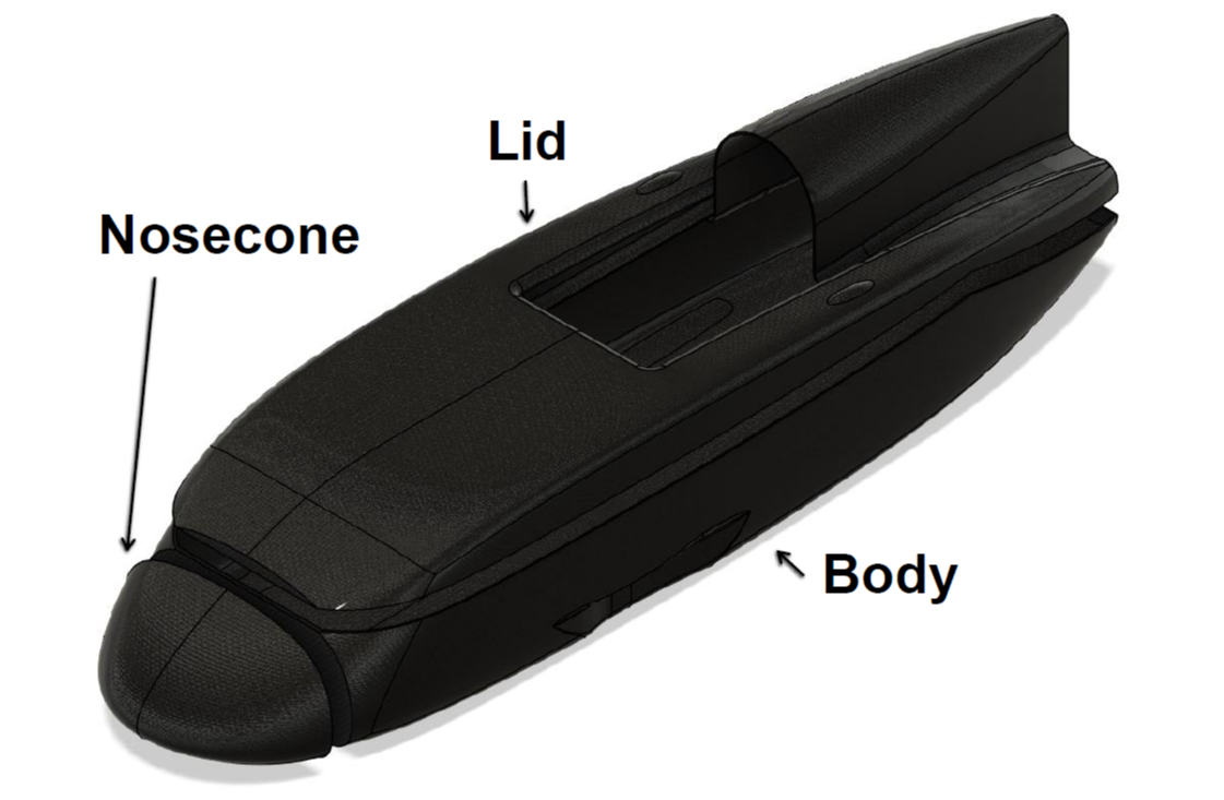
Simplified diagram of composite parts making up TMM.
Instead of featuring an internal structure responsible for load bearing, the optimised aerodynamic surfaces described on a previous project page are also used as the template for a composite monocoque. Ideally the chassis mass would be reduced to a minimum whilst still meeting all the safety regulations and structural requirements (plus appropriate safety factors). This is primarily to reduce rolling resistance, which is directly proportional to the total car mass.
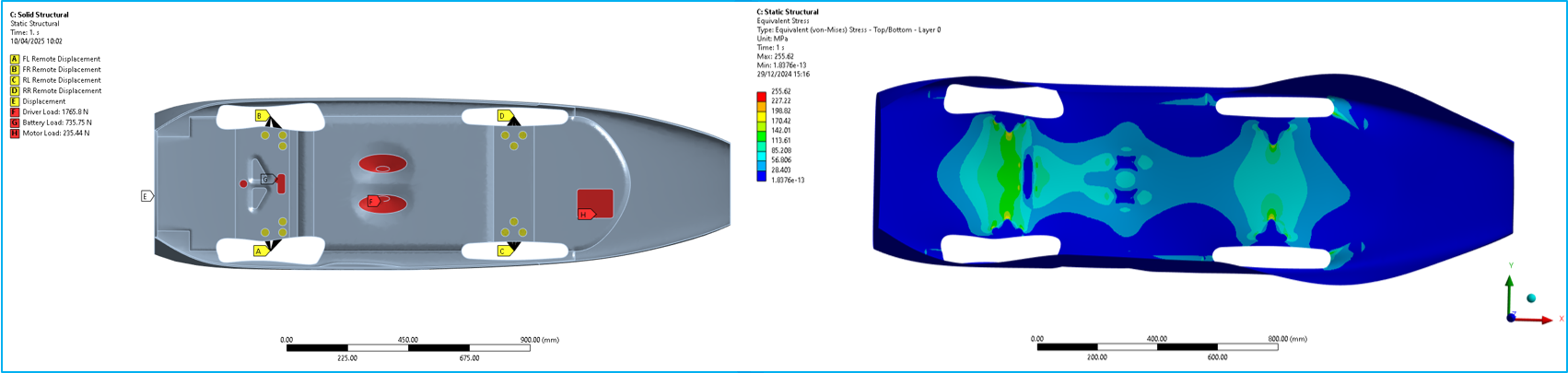
Example of boundary conditions and resulting stress distribution on outer carbon skin.
To achieve this goal an optimised composite layup needed to be designed, which was achieved using composite FEA tools in ANSYS ACP + Mechanical. Composite FEA is distinguished by material properties that are directionally anisotropic, as the tensile fibre direction in e.g. unidirectional carbon fibre reinforced polymers is far stronger than the orthogonal direction where the matrix (e.g. epoxy resin) contributes most of the strength. This difference manifests as pre/post-processing steps, where the exact carbon fabric layup is defined to pre-determine material properties, and the solved problem post-processed using composite specific failure criterion to determine whether e.g. the foam core sandwich has failed, or the fibres themselves have snapped.
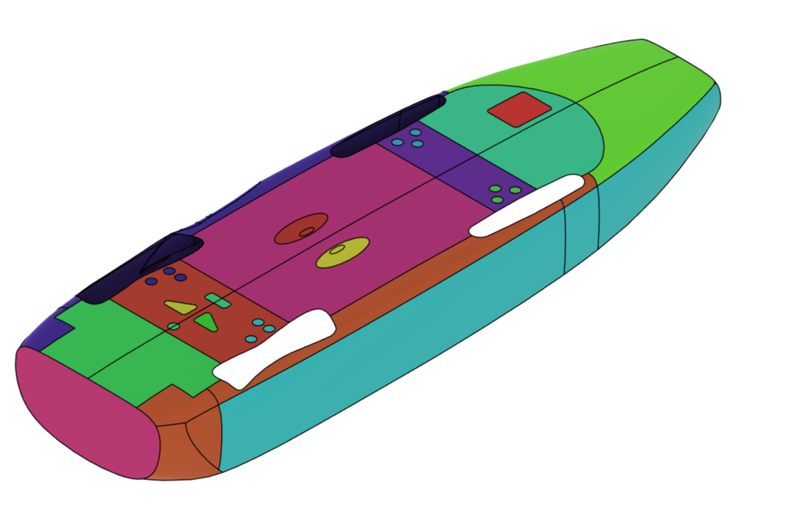
Upsidedown image of the surface splits used to define composite layup definition.
Given the individual fabric sheets used in the layup would have to be hand cut and laid in a garage, it was infeasible to automate the optimisation of the shapes, as such the aerodynamic surfaces were split manually, and informed steps were taken at each iteration to improve the layup. With each iteration the total car mass was reduced whilst maintaining stiffness and stress targets – ultimately bringing the predicted chassis mass down from ~14kg to 8.5kg.
Fabrics used were 195gsm spread tow, 200gsm plain weave, 300gsm uni-directional and 200gsm 2x2 Twill (for regions of high curvature). 5, 10 and 25mm 75kg/m3 PVC foam was used as sandwich to increase stiffness around the car. PEI plastic inserts were used to provide strong mounting points for internal structures without risking galvanic corrosion when combined with carbon fibre. IN2 infusion resin from Easy Composites was used and cured at 30 degrees C.
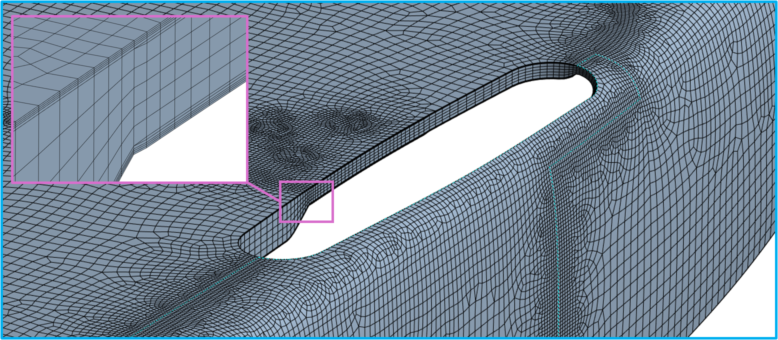
Example of 3D solid mesh around rear wheel cutout.
Extensive mesh and Boundary Condition (BC) dependency studies were carried out leading to a collection of 9 loading/BC cases that were run per iteration. 2D shell elements were used to quickly iterate designs at low computational cost, before 3D solid elements were employed to further verify results, using distinct elements for every unique fabric layer, and multiple elements across thick foam core regions.
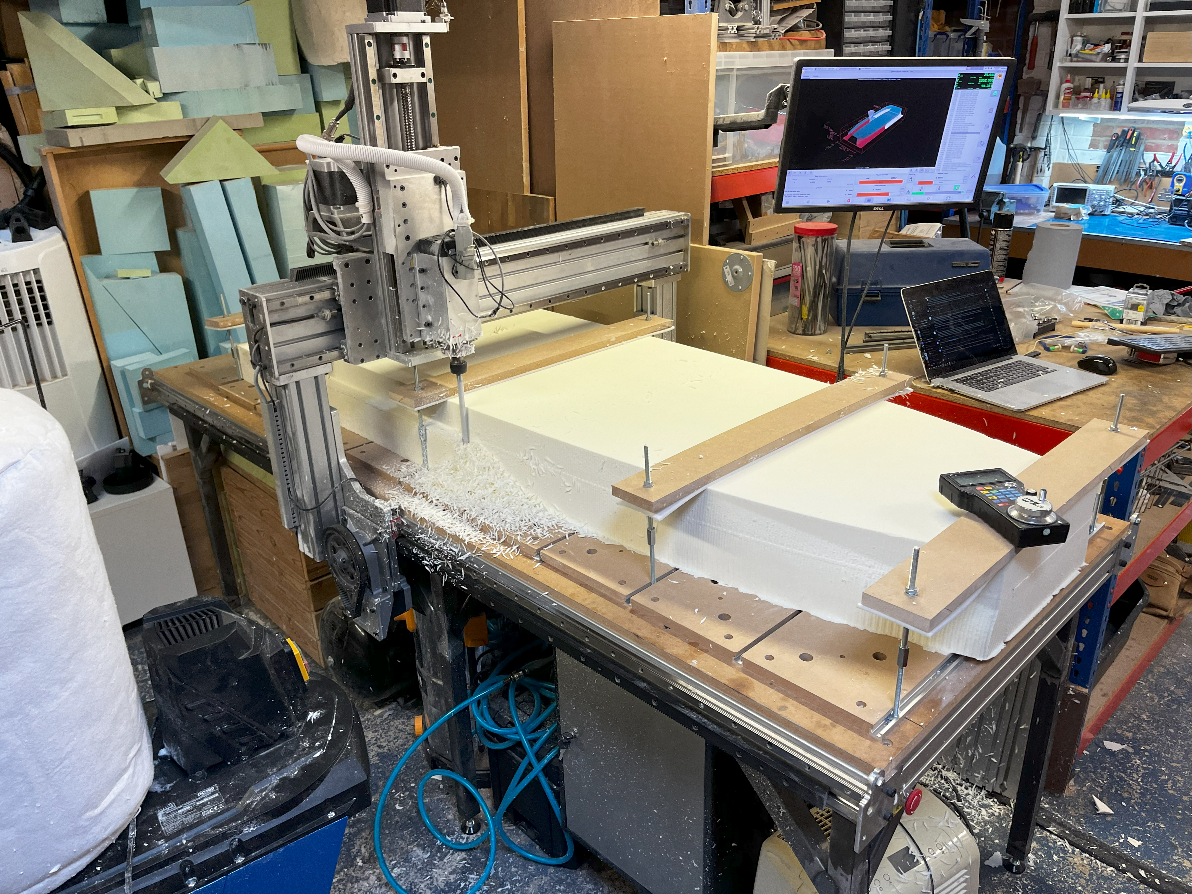
Chassis plug being machined on custom built CNC router.
A positive male plug was constructed using lightweight insulation foam machined on a custom-built CNC router. A split female chopped-strand fibreglass-polyester mould was pulled from this plug. Carbon fibre was then layered into the mould and epoxy resin infused to produce the chassis. The chassis was infused in my front living room to keep temperatures high during both inner/outer skin infusions and the secondary foam bonding stages.
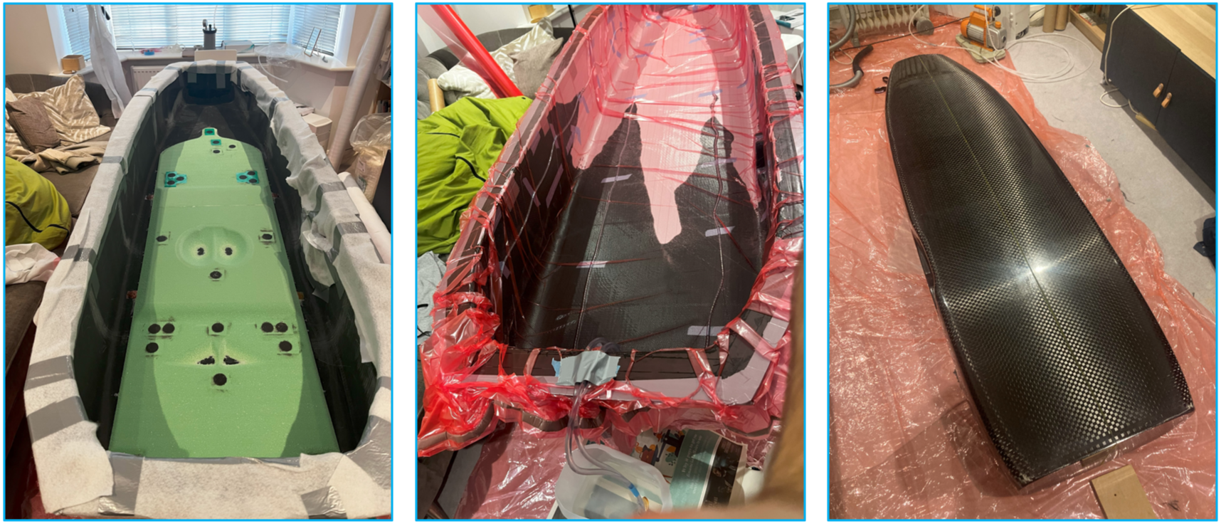
Chassis being resin infused in my living room, resulting in an extremely high quality gloss finish without pinholes.