Aerodynamic development with CFD
The power consumed overcoming aerodynamic drag goes up with the cube of velocity, so the faster we want to travel the lower the drag coefficient and reference area of our car needs to be.
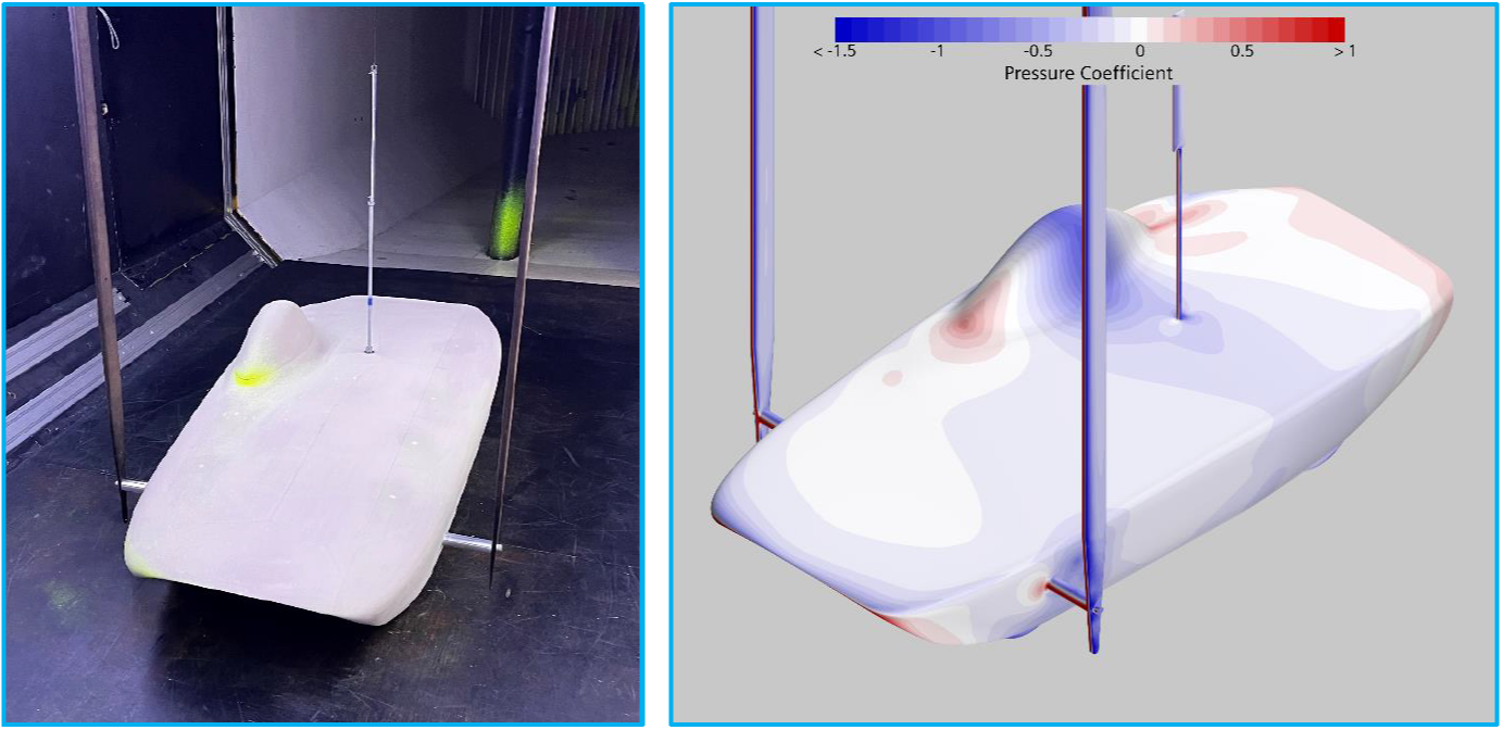
World Solar Challenge car wind tunnel model with corresponding CFD used for validation.
Extensive aerodynamic development was performed on TMM as part of my third-year (bachelors equivalent) dissertation project. The backbone of this development was validating the CFD approach on an aerodynamically similar World Solar Challenge model that the University of Southampton already owned. This was done in the 7’x5’ wind tunnel at Southampton, and proved the CFD approach could capture both the absolute drag values and the relative change in drag when sweeping the tunnel model through different onset angles.
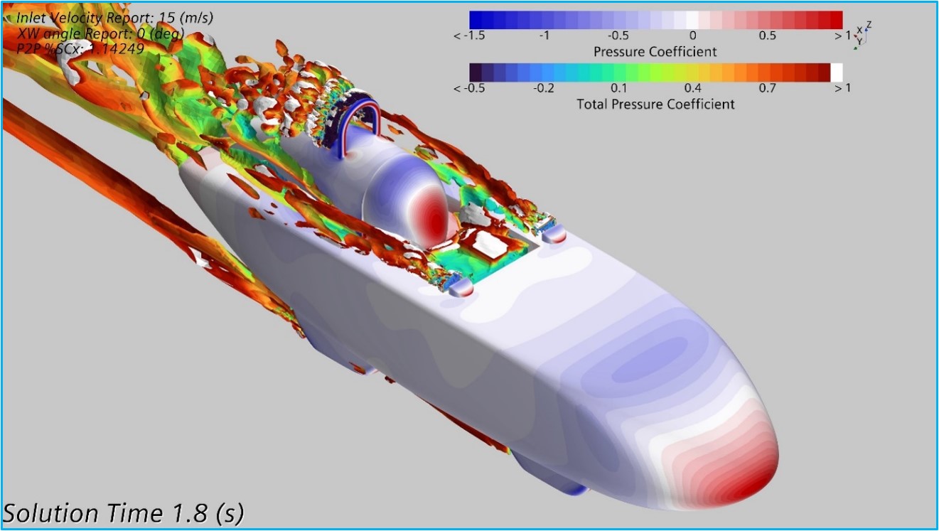
TMM initial design - DDES CFD result showing isosurfaces of Q-Criterion.
All the necessary steps, including extensive mesh dependency studies, were conducted to verify the numerical approach being taken was robust and efficient. The cell counts for studies ranged between 10-25 million on simple steady state cases and increased further when investigating transient effects. With confidence in the CFD methodology, and validated results, it was then used to extensively optimise the shape of TMM.
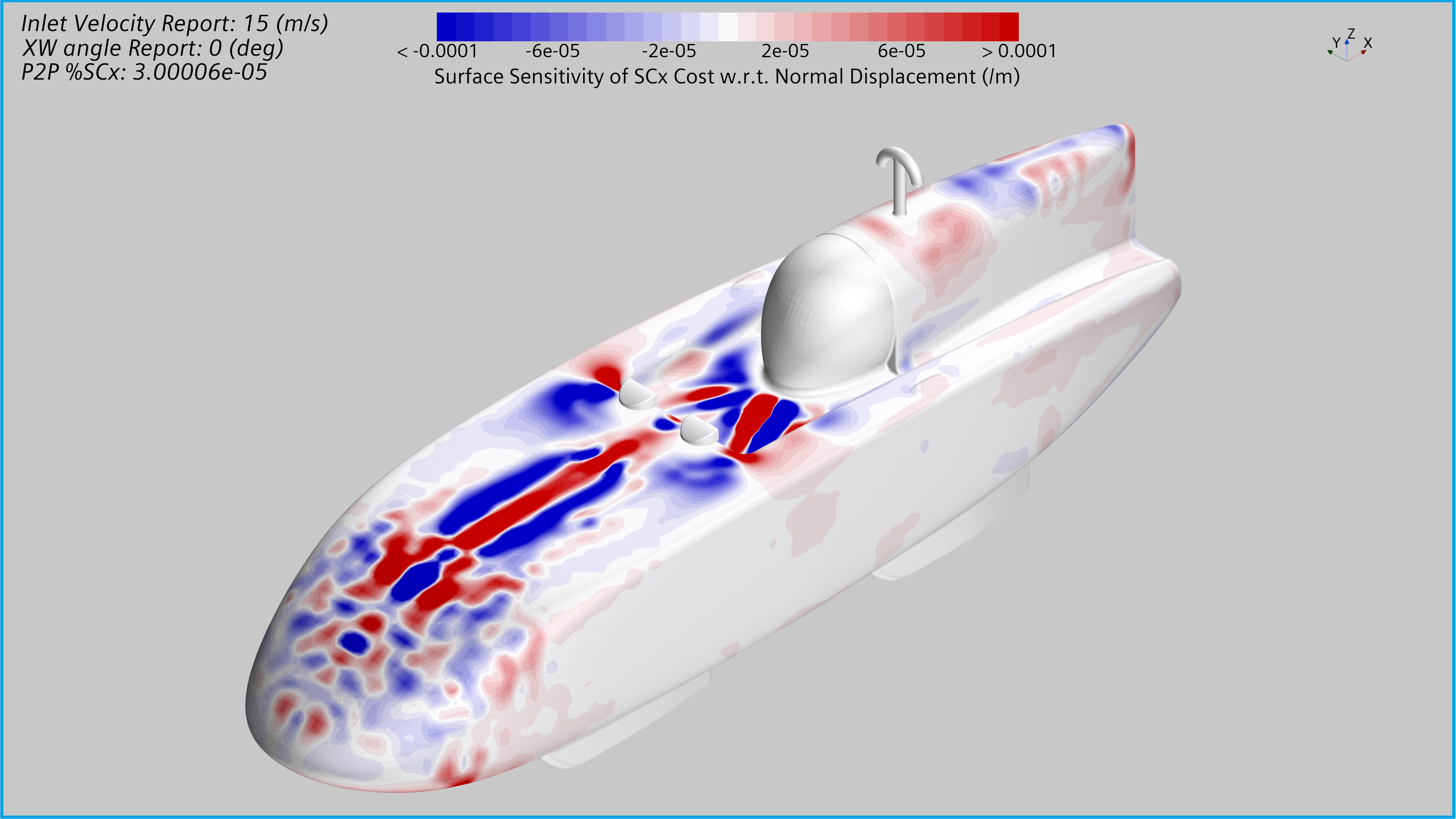
Adjoint solution surface sensitivity used to inform manual optimisation iterations.
RANS based methods were used for most of the development, with DDES being used periodically to verify that the drag improvements developed in RANS were manifesting when considering the transient behaviour seen around the cockpit and rollbar regions. Although optimisation was done predominantly manually, additional adjoint studies were undertaken to check whether obvious areas for improvement were being missed.
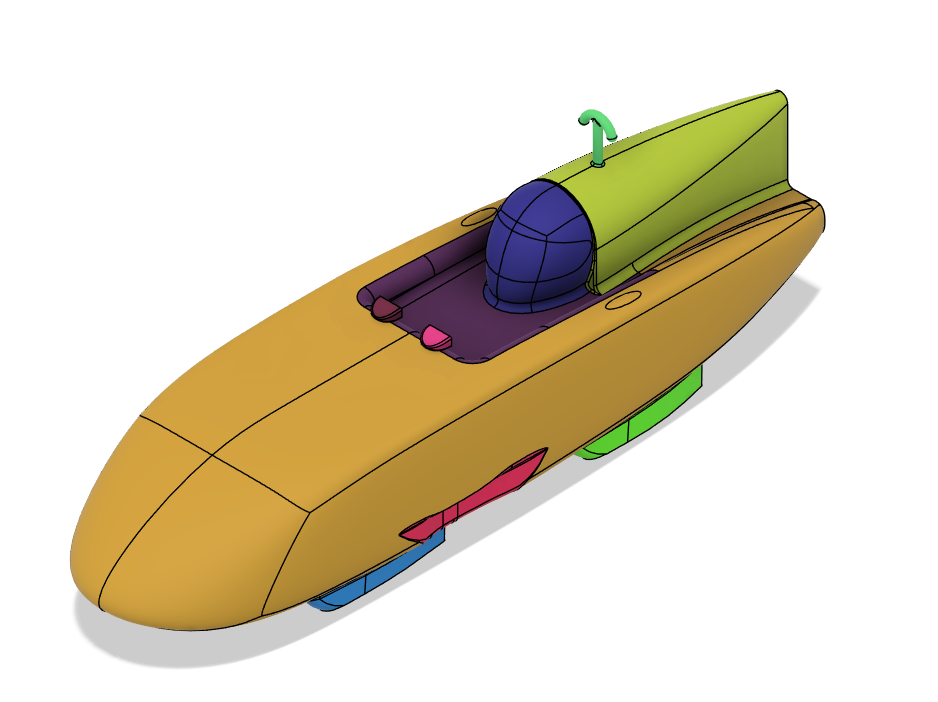
CFD surface model with coloured appearances corresponding to face names
To aid in the development significant automation was implemented, including writing custom Autodesk Fusion plugins to allow the ‘appearance’ features exported in .step files to be used to name walls for automatic recognition in Star-CCM+. This allowed the whole pre- through post- to be completely automatic once the CAD model was exported, only requiring moving the relevant files onto the University HPC (IRIDIS5) and submitting the job to the scheduler. Up to 120 cores were used for each simulation. Star-CCM+ was automated with custom written Java macros, rather than the often useful but inefficient ‘record macro’ method.
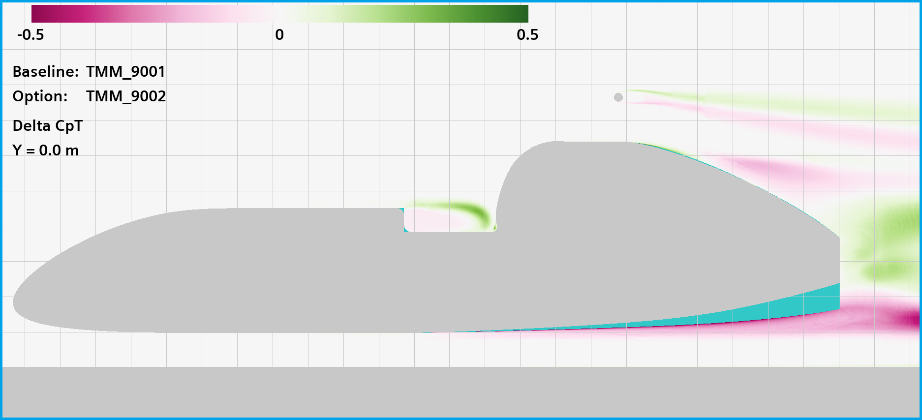
Delta image of CpT (at longitudnal symmetry plane) showing the change in lower/mid wake with a raised tail underside.
On top of this, additional post-processing scripts for computing image ‘deltas’ were written in Python. This allowed direct comparison of aerodynamic flow fields in a computationally efficient manner, as subtracting two volumetric flow fields on different grids requires more steps and computational time that operating on the pixels in a post-pro image.