A taster of interesting sub-projects that make up the design and manufacture of TMM.
Aerodynamic development with CFD
The power consumed overcoming aerodynamic drag goes up with the cube of velocity, so the faster we want to travel the lower the drag coefficient and reference area of our car needs to be.
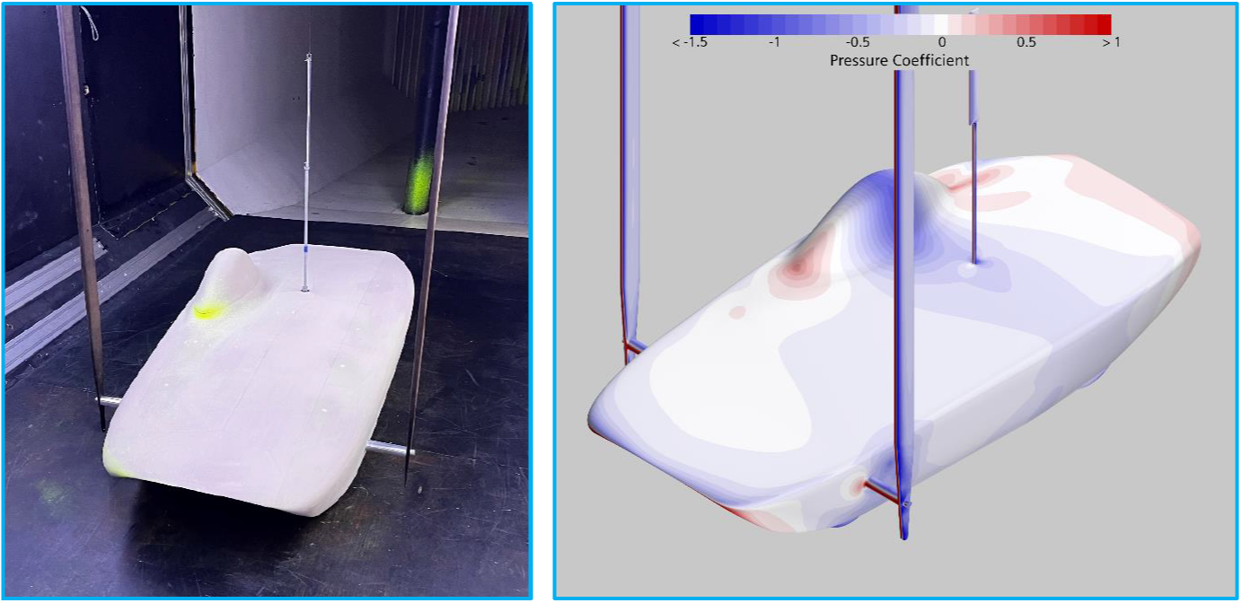
World Solar Challenge car wind tunnel model with corresponding CFD used for validation.
Extensive aerodynamic development was performed on TMM as part of my third-year (bachelors equivalent) dissertation project. The backbone of this development was validating the CFD approach on an aerodynamically similar World Solar Challenge model that the University of Southampton already owned. This was done in the 7’x5’ wind tunnel at Southampton, and proved the CFD approach could capture both the absolute drag values and the relative change in drag when sweeping the tunnel model through different onset angles.
Chassis composite FEA and build
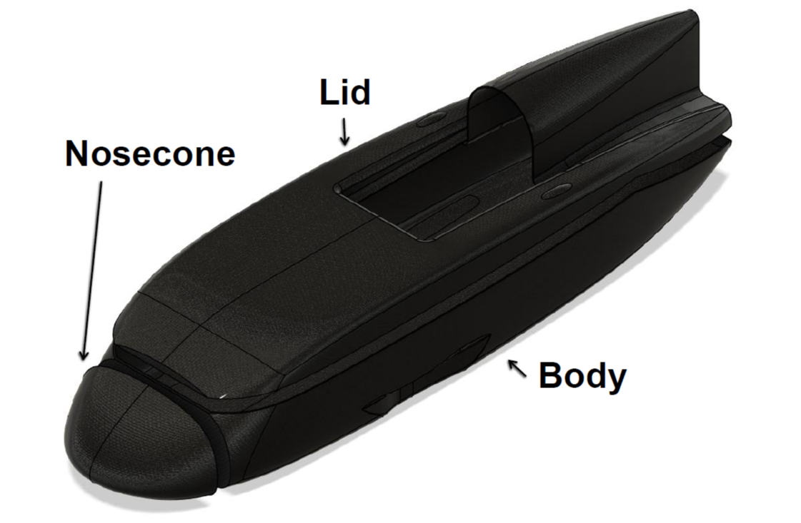
Simplified diagram of composite parts making up TMM.
Instead of featuring an internal structure responsible for load bearing, the optimised aerodynamic surfaces described on a previous project page are also used as the template for a composite monocoque. Ideally the chassis mass would be reduced to a minimum whilst still meeting all the safety regulations and structural requirements (plus appropriate safety factors). This is primarily to reduce rolling resistance, which is directly proportional to the total car mass.
Differentiable Lap Time Simulation with Optimal Control
This page briefly overviews the development of a Lap Time Simulation (LTS) tool using optimisation techniques paired with automatically differentiable dynamics to determine the true limit of race car performance.
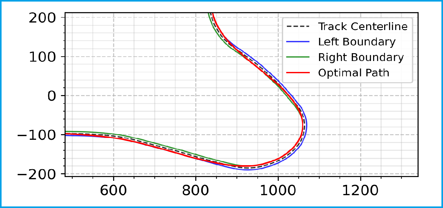
Computed optimal Greenpower racing line at Goodwood's 'Lavant' corner.
When improving Greenpower cars certain directions are obvious, e.g. reduce drag and reduce mass (without compromising safety). However, there are more nuanced engineering decisions that need to be made, such as: what is the optimal way to deploy your limited battery energy around a lap, considering hills, headwinds and corners?
Topology optimisation of the front wheel structure
The metallic components on the car are designed to be lightweight to reduce the rolling resistance experienced by the tyres, all whilst maintaining appropriate safety factors.
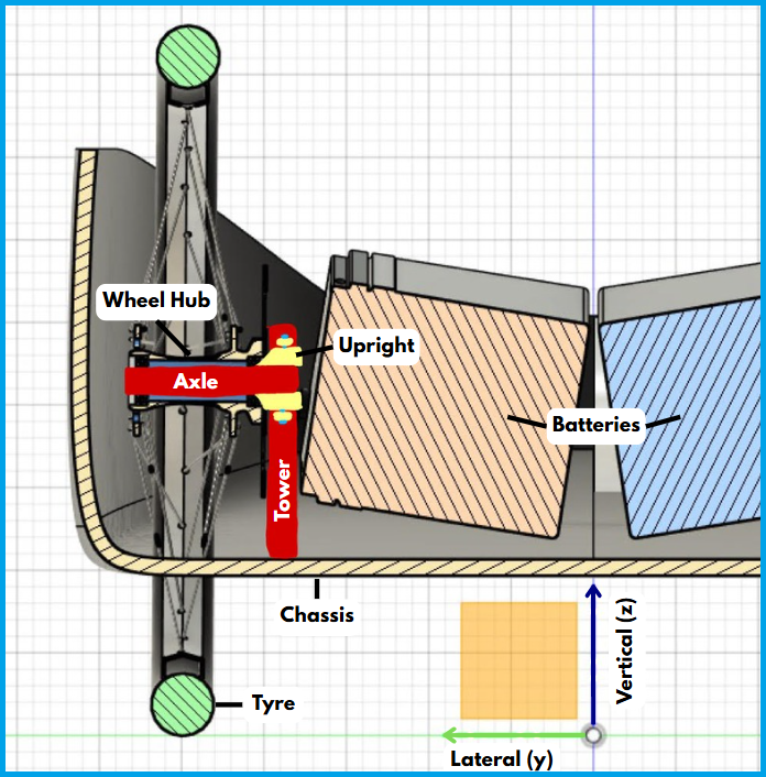
Cross section through the front axle showing the limited design space that the front structure can occupy.
The batteries on TMM are placed between the two front wheels at specific angles to exploit regulations for aerodynamic gain. This leaves a very small design volume for the structure (tower + upright) holding the front axles to the base of the monocoque chassis.
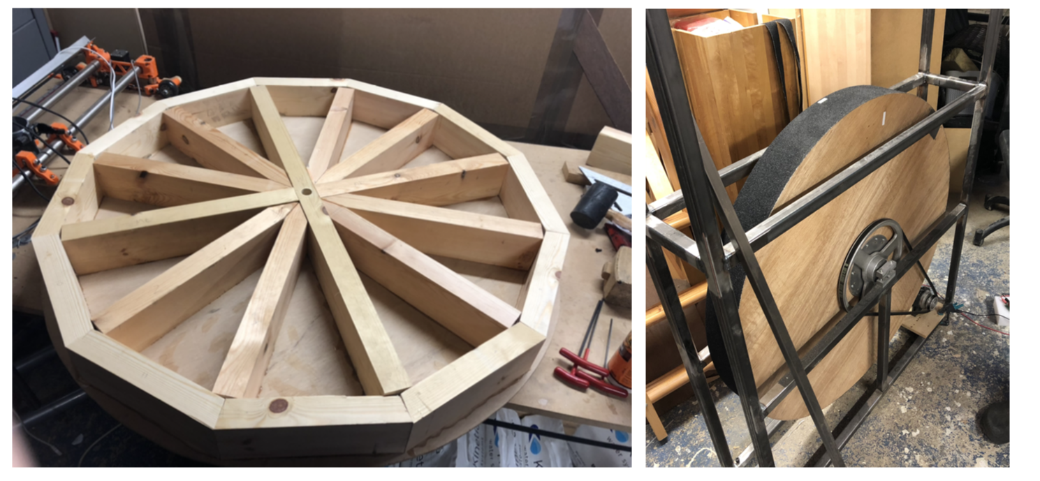
Tyres - testing rig and selection
In Greenpower, overcoming rolling resistance makes up a significant portion of the energy consumed over a race. The style of cars means unexpected tyres are often used, e.g. those from Brompton bicycles. Given the lack of high-performance Brompton bikes, there has been very little testing on their tyres rolling resistance, and so we took it upon ourselves to build a test rig and determine which tyres were the best.
Internal structure and final assembly of rolling resistance test rig.